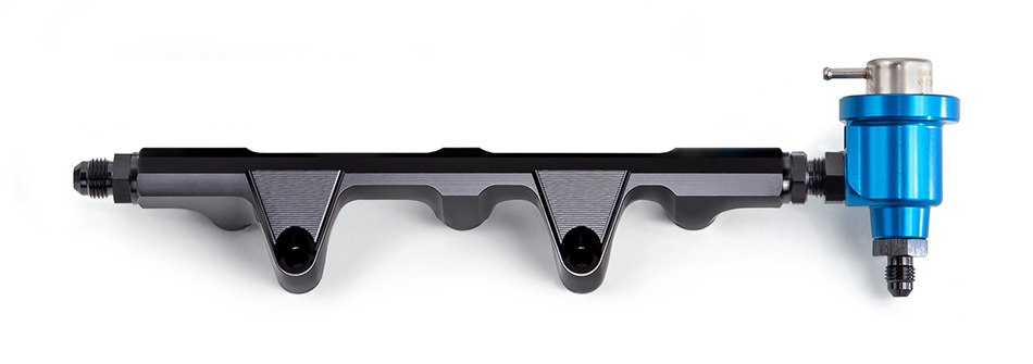
Fuel Rail Kit Contents and Descriptions
Fuel Rail Upgrade Kit (OE Feed line) – Kit includes fuel rail and adapter fitting for use with stock fuel line.
Fuel Rail Upgrade Kit (AN-6 Feed line) – Kit includes fuel rail and Teflon lined AN-6 feed line.
Fuel Rail + Pulsation Damper Kit – Kit includes fuel rail, Teflon lined AN-6 feed line and pulsation damper.
Fuel Rail + Regulator Kit – Kit includes fuel rail, Teflon lined AN-6 feed line, Teflon lined AN-4 return line, 3 bar regulator, in tank regulator block off plug.
Fuel Rail Only – Anodized aluminum fuel rail with AN-6 ORB inlet and outlet.
Regulator / Pulsation Damper – Combination 3 bar (43.5 psi) fuel pressure regulator and pulsation damper with AN-6 ORB inlet and AN-6 ORB outlet.
Fuel Rail Installation Guides
2017-2022 Can Am Maverick X3
2 seat install Instructions
4 seat install Instructions
Fuel Rail Tech
A fuel rail serves the purpose of distributing fuel to individual injectors. In isolation, this is a simple task, easy to accomplish with nearly any size shape or material as long as it is fuel resistant. Simple as it is, complexity arises when we consider it as part of a complete system.
In this system, we have fuel injectors that open and close very quickly. Using the ID1050 as an example, it opens fully in less than 1/2500 of a second. In this period of time, the flow transitions from zero to 1050cc/min. This abrupt change in flow results in a pressure drop in the system as the entire mass of fuel from the outlet of the fuel pump to the tip of the injector must be accelerated to fill the void.
Once this mass is accelerated to a velocity that maintains the 1050cc/min flow rate, it must then come to a stop as the injector closes, which also happens in less than 1/2500 of a second. This causes a sharp rise in pressure.
In extreme cases these pressure drops and spikes can exceed the static fuel pressure of the system, leaving pressure in the fuel rail at zero for microseconds at a time.
The vehicle manufacturers lessen these disturbances by utilizing compliant fuel lines, adding pulsation dampers to the fuel rail, or both. In some cases they do neither, accounting for the resulting fueling errors in the calibration.
While this provides for reasonably correct fueling on a stock vehicle, it is dependent on the characteristics of the system remaining constant. As soon as we install high flow injectors the amplitude of the pulsations increase. The larger the fuel injector, the greater the increase.
Using the Honda Talon as an example, upgrading from stock injectors to the ID1050 results in the average fuel pressure during the injector open period dropping 20% below regulator pressure, resulting in a 9.5% lean condition at wide open throttle.
While this can be accounted for in the calibration, it creates a unique problem on odd fire engines as the pulsations caused by opening and closing of any one injector affect pressure during the open period of the rest. Due to the differing time period between firings, individual cylinder fueling is skewed to such a degree that all stock 2 cylinder UTV calibrations include individual cylinder corrections exceeding 10%.
Care to guess what happens when we install injectors that are 2 to 3 times larger than stock?
In addition to the individual cylinder skew on odd fire engines, we run into problems with model-based systems like the Polaris and Can-Am which include injector flow rate as part of a complex calculation.
When average fuel pressure during the injector open period is less than modeled pressure, values in the VE table must be artificially inflated to maintain the requested air fuel ratio. This introduces errors in the load calculation which ultimately affect spark timing, wastegate control, drive by wire throttle opening, and a slew of other parameters that are dependent on accurate air and fuel flow numbers.
To address these problems, all Injector Dynamics fuel rail kits intended for use with larger injectors include a regulator/damper installed on the rail.
Whether controlling fuel pressure by bleeding excess fuel, or acting solely as a damper, it will substantially decrease pressure pulsations. Being mounted on the rail, close to the injectors, it can respond more quickly than a tank mounted regulator which is too far from the source of the disturbance to reduce pulsations.
Fuel Pressure Tech
Modern fuel injected vehicles utilize a “dead head” or returnless style fuel system. In a returnless system, fuel is pumped into one end of the rail while the other end is plugged, or “dead headed”. The fuel pressure regulator is located in the fuel tank where it controls pressure by bleeding excess fuel directly from the pump to the tank.
A return style system locates the fuel pressure regulator on the fuel rail, opposite the inlet, and controls pressure by bleeding excess fuel back to the tank, the difference being that the fuel must travel from the pump, through the rail, then back to the tank.
Industry wide adoption of the returnless system is due to reduced temperature of the fuel in the tank, as it is not heated by the rail. This reduces evaporative emissions.
Unfortunately, this is not optimum for high boost racing applications.
In a returnless system, the regulator is referenced to atmospheric pressure, meaning that a 4 bar (58psi) regulator would maintain a constant pressure of 4 bar (58 psi) above atmospheric pressure.
This is problematic when we consider that the fuel injector is spraying into the intake manifold which is not at atmospheric pressure.
Using a stock 2020 Can-Am X3 RR as an example, consider two operating conditions:
1. Idle – At idle, pressure in the manifold is 0.4 bar (6 psi) below atmospheric. The pressure in the fuel rail is 4.5 bar (63.5 psi) above atmospheric. The pressure difference between the injector inlet and outlet (Differential Pressure) is: 4.5 – (-0.4) = 4.9 bar (69.5 psi)
2. Wide Open Throttle, Full Boost – At wide open throttle, pressure in the intake is 1.4 bar (20 psi) above atmospheric, while pressure in the fuel rail is 4.5 bar (63.5 psi) above atmospheric. The pressure difference between the injector inlet and outlet is a mere: 4.5 – 1.4 = 3.1 bar (43.5 psi)
The end result is that the injector flows 26% less at full boost than at idle! This is barely manageable at stock boost levels, and gets worse as boost is increased. At 30 psi boost, differential pressure across the injector is reduced to 33.5 psi. This decreases the injector flow rate by a further 14%.
Think about that…we cranked up the boost by an additional 10 psi, substantially increasing our fuel flow requirement, and our injector flow rate went down by 14%!
As the fuel flow requirement increases, the injector flow decreases, and as the fuel flow requirement decreases, the injector flow increases. This is opposite of what is needed to properly fuel the engine.
The “fix” is to install larger injectors which provide greater flow, but this creates an additional problem which is that the injector is now too big to provide proper control at idle and cruise.
The solution is to address the root cause by converting to a MAP referenced return style system.
In comparison to an atmospheric referenced returnless system, a MAP (Manifold Absolute Pressure) referenced return style system includes a rail mounted regulator which is referenced to manifold pressure via a short length of hose.
The MAP referenced return style system provides fixed pressure above that in the manifold, the end result being that differential pressure across the injector remains constant, as does the injector flow rate.
It is for this reason that all Injector Dynamics fuel rail kits intended for use in boosted applications include a rail mounted MAP referenced fuel pressure regulator.


![]()
![]()


